
The diode I have used is a 1N5819 1A Schottky Barrier Rectifier which is a type of diode that allows both very fast switching and low forward voltage drop which is perfect for speed control using PWM. This transistor has a max current rating of 1Amp.

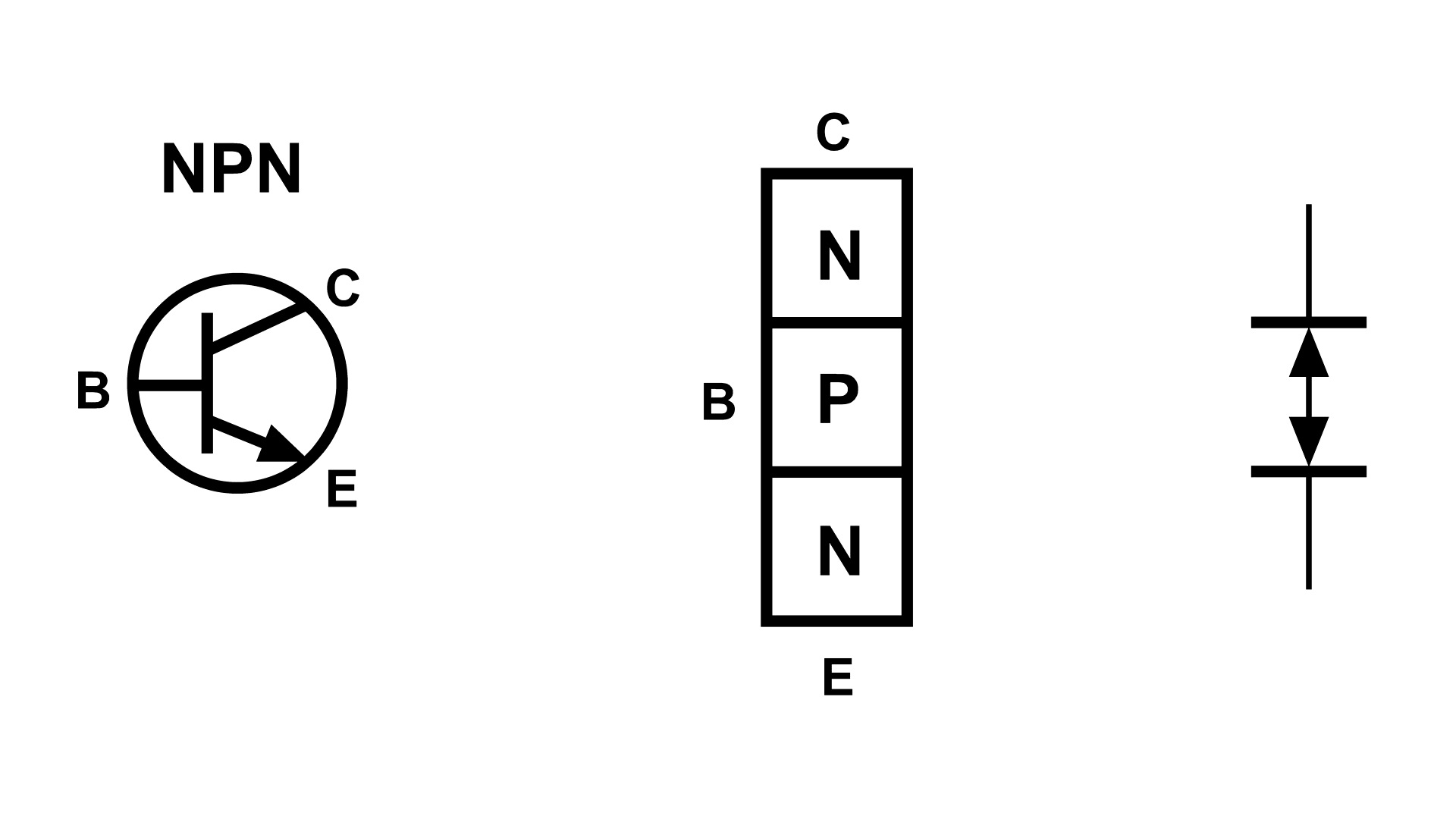
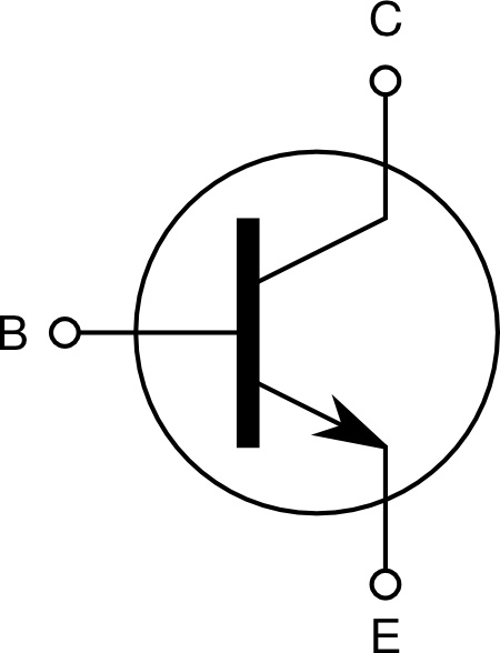
The required operating current will be between the Zero Load and the Max Load current so depending on what you want to drive with the motor you can determine a suitable transistor spec.Īs I'll be using this motor circuit to power an auger in a future fish feeder project, the Zero Load of 510mA will not be exceeded by more than 100mA so I'm going to use a BD139 NPN transistor (1st image). The current reading should now be much higher. Switch on the power supply and the motor will fail to start due to the physical resistance.Now switch off the power supply and hold the motor pinion so that it has a high physical resistance.Switch on the power supply and read the current on the Multimeter - This is the Zero Load motor current.Connect the motors second terminal to the power supply ground wire.Connect the Multimeter ground (black wire) to one of the motor terminals.Connect the Multimeter positive terminal (red wire) to the power supply positive wire which we previously marked with tape.Place the Multimeter red wire to the Amperage port and set the meter to read Current.Tape to mark the power supply positive terminalĪfter determining the positive wire from the power supply in Step 1 we can now determine the spec for our transistor that will be used as the motor control switch and the diode required for motor flyback.Multimeter to determine the positive terminal of the power supply and the minimum current requirement of the motor.Diode to protect transistor for motor flyback (Refer to Step 2) - 1N5819 1A Schottky Barrier Rectifier.NPN Transistor (Refer to Step 2) - BD139 NPN.Power Supply (Choose your power supply based on the motors requirement - I found an old 12V power supply in my shed that does the trick).Arduino (I've used an Arduino Micro but any Arduino will suffice).Basic Arduino Code to control the motor to Start, Stop and control the speed of your motor using Pulse Width Modulation (PWM).

Build instructions including images and links circuit io where you can simulate the project before ever building it.!.Determining specifications of required components.Determining the positive terminal of your power supply.If you need to control a DC motor that exceeds the max output of your microcontroller then follow this instructable and if you've any questions along the way I'd be happy to help.!


 0 kommentar(er)
